Construction
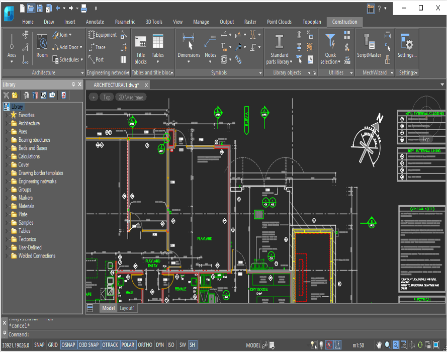
nanoCAD’s Construction Module enhances the nanoCAD platform with AEC drafting utilities and a library of standard parametric elements. It is designed to streamline the preparation of construction drawings and documentation. The nanoCAD platform offers a comprehensive set of basic and advanced design tools for creating and editing 2D/3D objects, providing multiple drawing and editing methods for most geometric elements. It serves as the foundation for building a more powerful CAD system tailored to your specifications.
Smart Drawing Elements
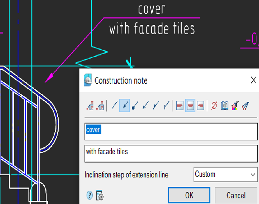
The Construction module includes a vast array of smart drawing elements to automate routine operations such as layout generation, sectioning, and detailing of buildings. Key features include:
Construction Features
Smart Drawing and Editing Utilities
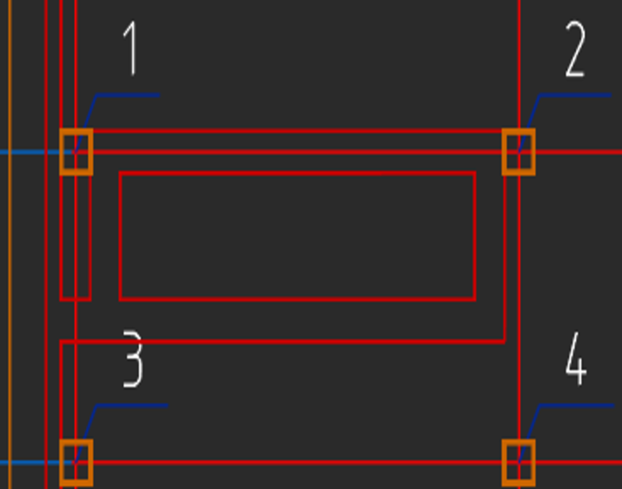
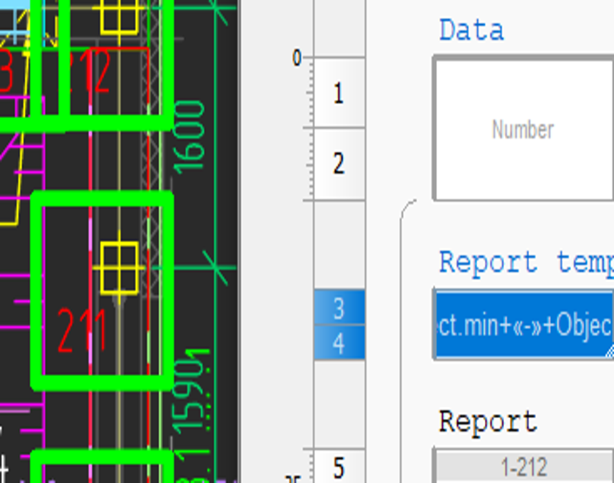
The Construction module converts entities that resemble tables (lines and text) into table objects. It offers utilities for automatically numbering drawing objects, adjusting selected areas, and creating custom objects with parametric properties.
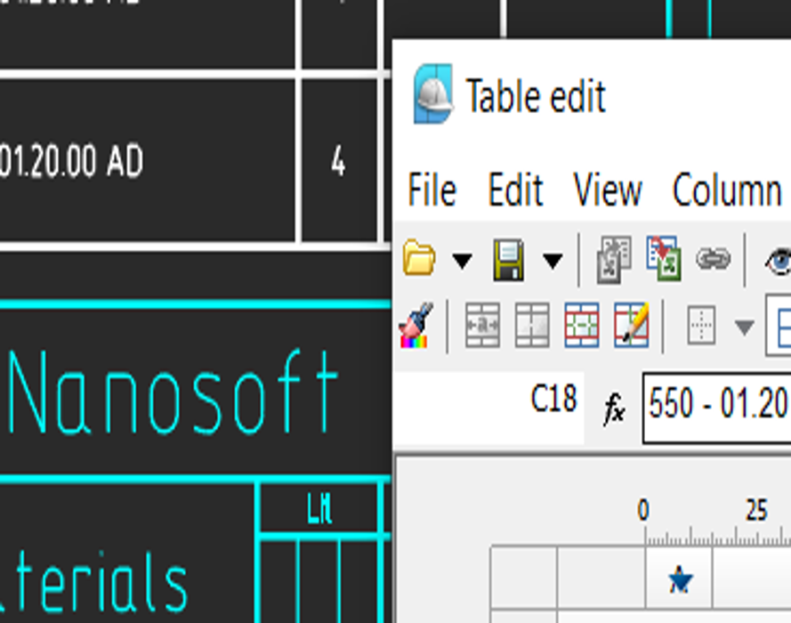
Powerful Table Editor
The Construction module features a robust built-in table editor that generates tables of any complexity. Users can convert tables imported from other CAD programs to nanoCAD’s format and recognize tables made from primitives. Table functions include:
Automatic Reports
The Construction module generates reports from lists, specifications, and object data in drawings. Reports access data extracted from objects, architectural components, design elements, blocks with attributes, and the Construction module’s library of parts, ensuring they are always up-to-date.
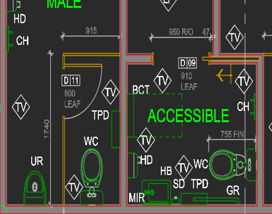
Architectural Layouts
The Construction module lays out building plans using discipline-specific tools and objects, including:
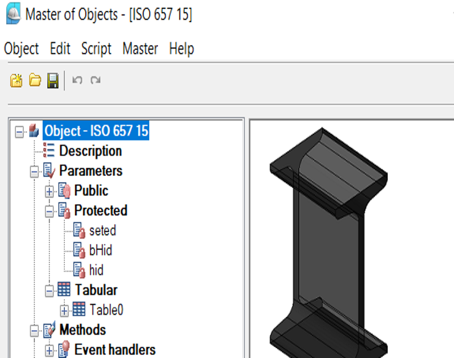
Create Custom Parametric Objects
Parametric objects improve upon dynamic blocks by offering dialog boxes with options in addition to grips for changing blocks. The Master of Objects allows you to edit library items and create parametric objects to meet your needs.
Parametric Design Elements
The Construction module employs objects that follow preset rules based on building project design requirements. All drawing elements that make up AEC objects (such as notches, lines, and text) contain parameters controlling their display and geometric configurations.