3D Solid Modeling
nanoCAD’s 3D Solid Modeling module enhances the nanoCAD platform with both direct and parametric modeling capabilities. It is designed for constructing 3D assemblies with 3D constraints and xrefs, and for handling sheet metal modeling. nanoCAD can be used independently as an affordable DWG editor or customized with essential modules such as Construction, Mechanica, Raster, Topoplan, and 3D Solid Modeling.
New in 3D Solid Modeling
The nanoCAD platform offers a comprehensive set of basic and advanced design tools for creating and editing 2D/3D objects. It provides multiple drawing and editing methods for most geometric elements, serving as the foundation for building a more powerful CAD system tailored to your specifications.

3D Solid Modeling Features
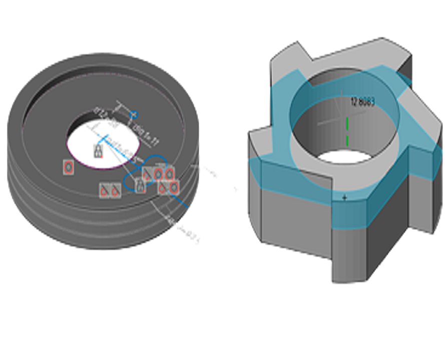
Parametric 3D solid modeling
nanoCAD’s parametric modeling mode allows engineers to build 3D geometry piece by piece. This design approach, common among MCAD applications like SolidWorks and Inventor, involves turning 2D sketches into 3D features while documenting design intent through constraints and geometric relationships. The history of the model’s construction is recorded in a history tree, accessible via an Inspector panel with its own set of tools.
Direct 3D modeling
nanoCAD’s direct modeling offers a WYSIWYG (what-you-see-is-what-you-get) approach, enabling designers to edit 3D models by pushing and pulling faces and edges. This method allows for easy alterations, facilitating rapid iteration and prototyping.
Natural 3D modeling UI
nanoCAD groups commands by modeling type: parametric, direct, sheet metal, and meshing. For instance, in parametric modeling mode, commands for creating 3D geometry based on parametric sketches are displayed. When switching to mesh modeling, commands for creating 3D surfaces become available. Commands applicable to all modeling forms, such as chamfers, rounds, Boolean operations, and construction geometry, are always displayed on the ribbon.
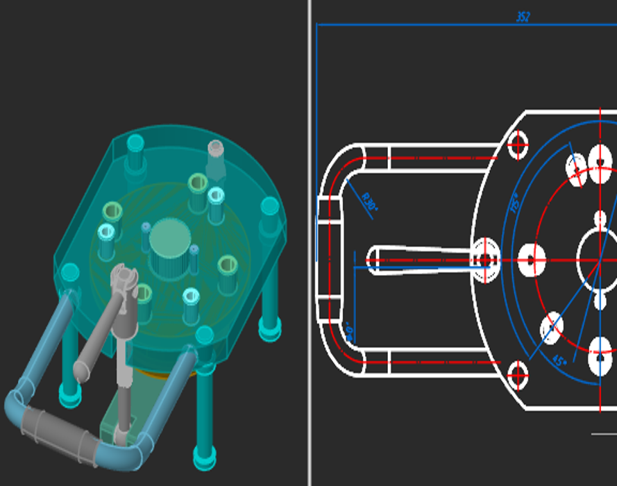
Associativity of 3D models and drawings
The associative relationship between models and their projections allows users to focus on designing in a 3D environment, with 2D graphics mainly used for drawing design. Any changes to the 3D model are reflected in the drawings, and design elements made in 2D graphics correspond to these changes.
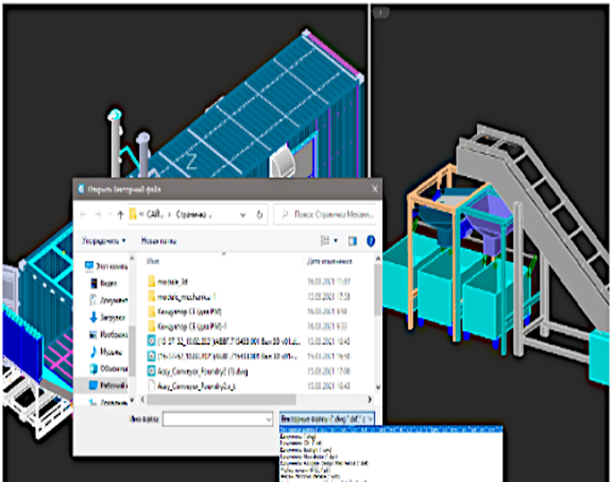
Model exchange via Import/Export
Models created using the 3D Module can be exchanged with most CAD systems and exported to 3D printers, CNC machines, and web-based viewers. Supported formats include:
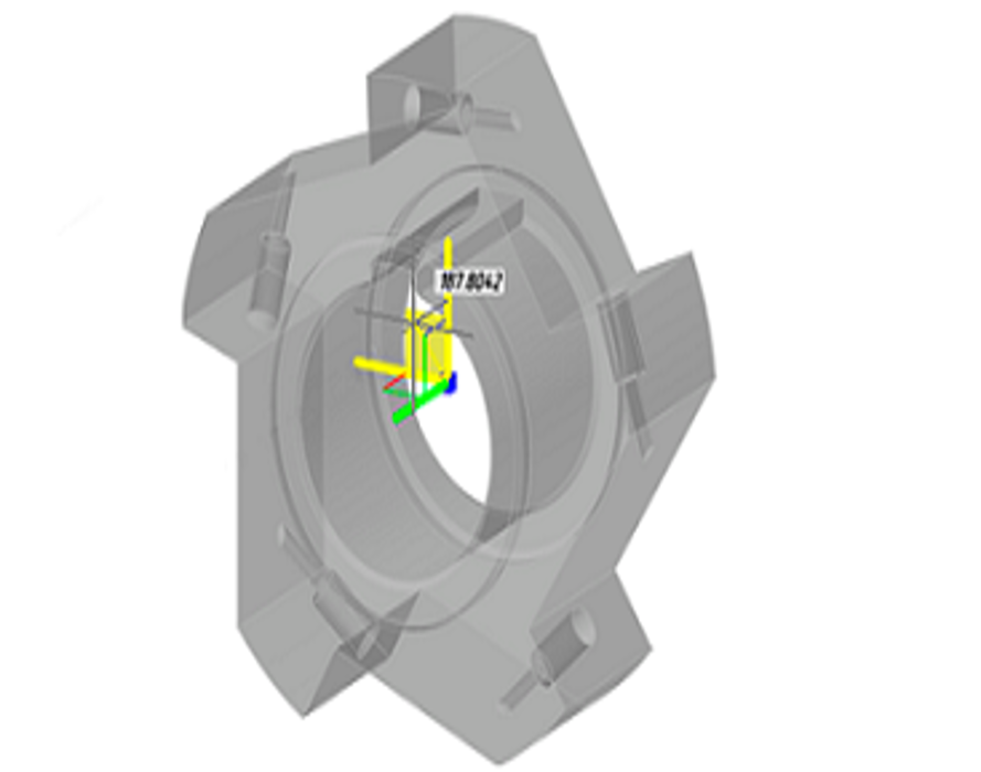
Bounding prisms
nanoCAD uses 3D clipping to display the insides of models and isolate parts. Each model space viewport can hold a bounding prism, a 3D volume outside of which drawing elements are not displayed. Prisms can be edited, deleted, and disabled. When disabled, elements outside the prism become visible again; disabled prisms are stored in the drawing for future use.
